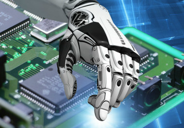
Circuit board is a kind of electronic circuit, which is very common in our life. There are such items in computers, mobile phones and refrigerators. Printed circuit board is also called pcb board aluminum substrate, high frequency board, ultra-thin circuit board, ultra-thin circuit board, Printed (copper etching technology) circuit boards, etc., are the supports for electronic components and the provider of circuit connections for electronic components. The most common printed circuit boards use the method of printing etching resists to produce circuit patterns and circuits, so they are called printed circuit boards or printed circuit boards. Because people want smaller products, mobile phones are getting smaller and smaller, computers are getting smaller and smaller, and the circuit boards of FS Technology have become more and more refined. With the advent of the 21st century, production technology has become more and more developed. The vast majority of PCBs now use etch resists (lamination or coating), and after exposure and development, PCBs are made by etching.
The working principle of FS technology pcb
PCB is manufactured by many processes, mainly including the following processes, pads, electrical boundaries, mounting holes, vias, components, connectors, wires, filling, etc. If the pcb is distinguished according to the number of layers, it can be divided into the following common types: pcb single-layer board (Single Layer PCB), pcb double-layer board (Double Layer PCB) and pcb multi-layer board (Multi Layer PCB) three types . The main processes of these pcbs have the following functions, each of which is essential:
There are metal vias and non-metal vias, where metal vias are used to connect component pins between layers - vias
for fixing pcb-mounting holes
Components used for connection between pcbs. -connector
Used to determine the size of FS Technology's pcb, all components on the pcb must not exceed this boundary - electrical boundary

The surface copper foil conductive layer is separated by the insulating material of the board base, so that the current flows in various components along the pre-designed route to complete functions such as work, amplification, attenuation, modulation, demodulation, coding, etc. - the working principle of pcb
Metal Hole-Pad for Soldering Component Pins
Electrical network copper film-conductor for connecting component pins
Copper plating for ground network can effectively reduce impedance-filling
FS technology pcb production method
Although there are many methods of processing and making PCBs, the traditional rapid board making methods can be mainly divided into two categories: physical methods and chemical methods:
① Physical method:
By using many utensils and power tools, the copper that is not needed on the circuit board is manually engraved. This method is not very good, time-consuming and labor-intensive, and has low accuracy. Of course, it is applicable if your circuit board design is relatively simple, but not for complex circuit boards.
Features: It is labor-intensive and time-consuming, the precision is not easy to control and there is irreversibility, and the operation requirements are very high. With the development of science and technology, fewer and fewer people use this method, and people are more inclined to use the chemical method.
② Using chemical methods:
This method is currently the most used method by FS Technology. People etch away unnecessary copper in a corrosive solution by covering a protective layer on a blank copper clad laminate. Of course, technology has made us more and more advanced. We have developed many ways to achieve the protective layer, the most traditional way of hand painting method, the method of pasting customized self-adhesive, the method of film sensitization, and the method developed in 2010. Thermal transfer printing PCB board method.
Features: The process is relatively complex, but the precision is controllable. It is the most widely used rapid plate-making method at present, but there are still many problems.
③ Hand painting:
Manually draw the shape of the circuit on the blank copper clad laminate with a soft pen or a hard pen. After drying, it can be put into the solution for direct corrosion.
④ Paste the sticker:
There are all kinds of stickers in the world that are made into strips and discs. Different stickers are combined on the blank circuit board as needed, and they can be corroded after they are glued.
⑤ Film sensitivity:

The PCB circuit board diagram is printed on the film by a laser printer, and the blank CCL is pre-coated with a layer of photosensitive material (coated CCL is sold in the market), and it can be exposed, developed, fixed and cleaned in a darkroom environment. Corrosion in solution.
⑥ Thermal transfer:
The circuit is directly printed on the blank circuit board by the FS technology thermal transfer printer, and then put into the corrosive solution to corrode.
To sum up: the previously used physical plate-making method is labor-intensive, time-consuming and low in precision, while the chemical rapid plate-making method has controllable precision, but the process is complex and not environmentally friendly. Regardless of whether it is a physical method or a chemical method, both of them require high operating skills, so neither can be regarded as a good method that can help engineers achieve "fast" board making.
Posted
Jun 14 2022, 06:57 PM
by
FSPCBA